GOQTT protocol
Establishing a connection
Just like with the MQTT protocol, there is a broker that listens for incoming connections on a defined port. Once a connection arrives, the device is connected to the server, however, it still has no ability to send and receive information until it sends its identification header.
The header that the device must deliver is in the form:
ClientID: <device identification>
After the connected device sends its identification, the broker can decide what to do with that connection. A whitelist or blacklist architecture can be implemented for server security, an additional auth header can be expected, and so on.
If the device identification is completely new on the server, a completely new structure will be created on the server to handle this connection and the delivery and receiving of messages can begin.
If the identification already existed on the server, the existing TCP connection will be terminated (if it exists) and the incoming TCP connection will be set as the main one for communication of all future messages over that connection. In this case, the connection returns to the previous state with all message subscriptions, and upon establishing the connection, it receives all missed messages on the topics it is subscribed to.
Sending messages
Communication within the protocol is done via TCP connection using JSON format. The client delivers messages to the server in the following format:
    {
        "type": <message type>,
        "topic": <topic>,
        "value": <value>,
        "qos": <qos level>
    }
Unlike the MQTT protocol, devices do not make a field with sender identification but that field is additionally appended on the server side.
Type
Within the defined protocol, the message type is identified by the type
field in JSON. The values this field can take are:
PUB Request by the client to publish a message to a topic, i.e., all subscribers of that topic.
The message must contain all fields. Example:
    {
        "type": "PUB",
        "topic": "temperature/home",
        "value": 23.45,
        "qos": 0
    }
SUB Subscribe to a topic by the client, i.e., the client requests from the server to receive all future messages that come to that topic.
The message must contain type and topic field. Topic is the topic the device will be subscribed to.
    {
        "type": "SUB",
        "topic": "temperature/home",
    }
After the server receives this message from the client, it starts receiving all future messages on that topic.
Instead of designing the full topic name, it is possible for the client to request all events that occur at the level below the defined one. For example, the client can send the following message:
    {
        "type": "SUB",
        "topic": "temperature/#",
    }
After sending this message, it becomes subscribed to all events that start with “temperature”, so it would receive events that occur at “temperature/home/room1”, “temperature/hospital”, etc…
ACK If a received message has QoS level 1 or higher, the client responds with this message so the server knows the message was successfully delivered.
    {
        "type": "ACK"
    }
LIVE Implemented event so the client can keep the connection alive via heartbeat method if there is nothing to send to the server.
    {
        "type": "LIVE"
    }
PING Event that is made so the client can test the connection with the server. After sending this message, the server responds with PONG message.
    {
        "type": "PING"
    }
QoS
QoS level serves to introduce a level of reliability in communication. QoS (Quality of Service) can take 3 different values - 0, 1, 2. Currently 0 and 1 are implemented.
QoS 0 denotes that the server simply delivers the message to subscribers without any testing. This is analogous to UDP communication.
QoS 1 denotes that we want the packet to be delivered at least once. This is ensured by the method that, when the client receives a QoS 1 message, it must respond with an ACK message.
Receiving messages
After the client subscribes to a certain topic, it starts receiving events that arrive on that topic. Events arrive in a form identical to that sent by the publisher, with the important modification that the server appends the sender.
The received message has the format:
    {
        "sender": "Weather Station 1",
        "type": "PUB",
        "topic": "stations/humidity",
        "value": 75,
        "qos": 0
    }
If the received message is QoS 0, the client has no obligation to reply to the server, however, if the received message is QoS 1 then the client must return an ACK message (2.2.1).
Broker design
For creating the broker, I decided to use the Go language for the following reasons:
-
Statically typed and compiled language
-
Direct access to pointers
-
Garbage collector
-
Well-developed network libraries
-
Extremely simple concurrency
The broker design centers around handling connections with clients in a concurrent manner. Each connection has its own goroutine (goroutine is a thread within the go runtime that it manages).
Each connection (incoming or established) is in a separate goroutine to function concurrently with all other connections. The broker puts a listener on each connection with a timeout of 1 second so that other functions can be executed if needed, and, if 60 timeouts pass on one connection without it sending a message to the server, that connection is closed because it has probably stopped functioning.
Since one of the most important parameters in network communication, and especially in the IoT world, is response speed (latency), I decided to use the so-called Worker Pool pattern for creating the broker. Each worker thread has access to a channel that receives the Job interface:
type Job interface {
    Run()
    Summary() string
}
Data processing is done by calling the Run() method which each Job structure must implement, and summary is used for logging.
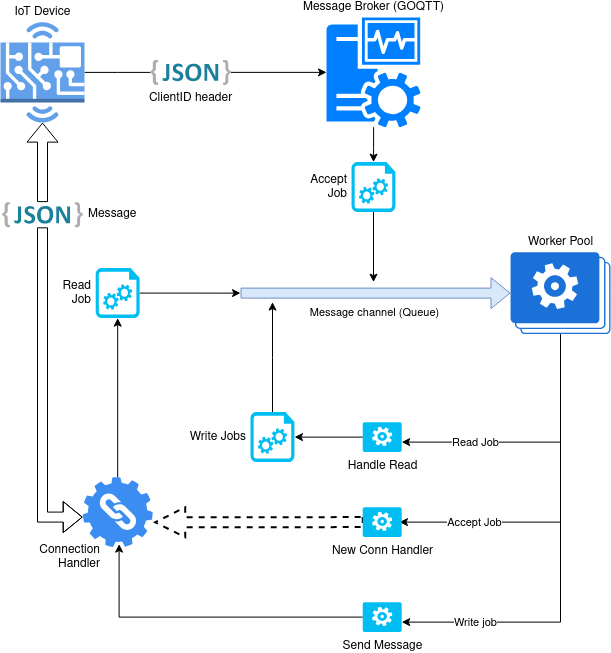
Accept Job
When a connection first arrives on the broker port, it runs ConnAcceptJob(). The Run task of this Job creates a new goroutine for talking on the connection by passing the connection to the HandleConnection() function. HandleConnection() expects the connection to authenticate with the ClientID header by which it then either creates a new structure for the connection or reconnects to an existing one. If it is a reconnect, all missed messages are delivered to the connection.
The connection handler then listens for incoming events on the connection. To know that the connection is alive, a heartbeat mechanism is implemented where a timeout is placed on listening and it is restarted every second. If the timeout counter reaches 60, the connection will be marked as stale and the server will close it. The client must handle this behavior by sending a heartbeat signal.
Read Job
If the connection sends a message to the server, a Read Job will be started which handles the JSON that the client sent. Depending on the fields, different internal events are executed on the broker. A special event is the PUB event which will find all clients subscribed to the topic specified in the message and will start a new Write Job for each Subscriber.
Write Job
When a PUB message arrives at an event, all subscribers of the topic specified in the message must receive the sent message. For each of these subscribers, a new Write Job is added to the message queue. During addition, the queue is completely locked for all operations. This ensures concurrency as well as message delivery in exactly the received sequence.
Deployment
The application can be deployed in 2 different ways.
GitHub
The first is cloning the github repository
(git@github.com:AdelSehic/goqtt.git) directly and running it.
    > git clone git@github.com:AdelSehic/goqtt.git
    > cd goqtt
    > go build .
    > go run goqtt
For this method, complete configuration of the config file within the config directory is required.
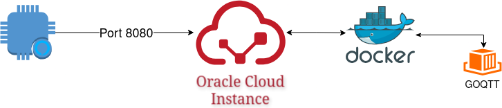
Docker
The application is dockerized on docker hub so it is sufficient to run
> docker run --rm -d --name goqtt -p 8080:8080 adelsehic/goqtt:latest
For the purposes of the project, the docker container is running on Oracle Cloud instance.
Publisher
This code implements a simple IoT (Internet of Things) application that reads temperature using a DS18B20 sensor, connects to a WiFi network and sends the read data to the server over TCP/IP protocol. Below is an explanation of each part of the code:
Libraries
First, it is necessary to include the libraries
        #include <WiFi.h>
        #include <OneWire.h>
        #include <DallasTemperature.h>
        #include <ArduinoJson.h>
WiFi.h: Used to connect the ESP32 microcontroller to a WiFi network. OneWire.h: Enables communication over the OneWire protocol, which is used for communication with the DS18B20 sensor. DallasTemperature.h: Provides functions for working with the DS18B20 thermometer. ArduinoJson.h: Enables easy creation and processing of JSON data, which is used for formatting messages sent to the server.
Pins
        #define ONE_WIRE_BUS 5
        OneWire oneWire(ONE_WIRE_BUS);
        DallasTemperature sensors(&oneWire);
In the first line of code, we define which GPIO pin on the ESP32 microcontroller we use to communicate with the DS18B20 sensor. Pin 5 is set as the data pin (data line) of the sensor. The DS18B20 sensor uses the OneWire protocol, where all data is transmitted over a single wire (in addition to power and ground). For communication to be successful, the microcontroller must know which pin it uses for sending and receiving data. The second line creates an instance of the OneWire class and connects it to the pin we defined (GPIO 5). This class enables communication with devices that use the OneWire protocol, like the DS18B20 sensor. OneWire is a protocol that enables communication with multiple devices over a single line. This class is fundamental for working with such devices. The third line creates an instance of the DallasTemperature class, which is specialized for working with DS18B20 sensors. This class uses the OneWire instance (passed as a reference &oneWire) for communication. Although OneWire enables basic communication, DallasTemperature adds functionalities specific to working with temperature sensors, such as reading temperature, managing multiple sensors on the same line, and configuring the sensor resolution.
Connecting to Wi-Fi
        const char* ssid = "adel";
        const char* wifipass = "adel1234";
        const char* server_ip = "140.238.215.2";
        const uint16_t server_port = 8080;
        const char* client_id = "Sjever 2";
        WiFiClient client;
First, the WiFi network name, known as SSID, is defined, which is set here to “adel”. This name is key because the ESP32 must know which network it should connect to. Then, to make the connection successful, the password of that network is added, which is “adel1234” here. These two pieces of data allow the device to connect to wireless internet. After the device connects to the network, it needs a server to send data to. The server address is defined using the IP address, which here has the value 140.238.215.2. For communication to be complete, it is necessary to define the port through which data will be exchanged; port number 8080 is used here. Additionally, the device has a unique identifier, called client_id, which is set to “Sjever 2”. This identifier allows the server to distinguish data coming from this device from data of other devices. Finally, a WiFiClient object is created, which represents the means for establishing connection and communication with the server. This object manages sending and receiving data over the network, making the ESP32 ready for communication.
Setup() function
void setup()
 {
     Serial.begin(115200);
     Serial.println("DS18B20 Temperature Sensor Example");
     WiFi.begin(ssid, wifipass);
     Serial.print("Connecting to WiFi ....");
     while (WiFi.status() != WL_CONNECTED)
         {
             delay(500);
             Serial.print(".");
         }
     Serial.println("\nWi-Fi connected!");
     sensors.begin();
     Serial.print("Connection to server ...");
     while(!client.connect(server_ip, server_port))
     {
         Serial.println("Connection failed, retrying in 5 seconds ...");
         delay(5000);
     }
     Serial.println("Connected to server!");
     client.println(String("ClientID: ") + client_id);
 }
The setup() function is the first part of the program that executes when the ESP32 device is turned on or reset. Its main task is to prepare the device for work, establish WiFi connection, connect to the server, and initialize the temperature sensor. The first line in the function is Serial.begin(115200), which enables serial communication with the computer via USB connection. This communication is used for printing messages to the serial monitor, which helps in tracking program execution and debugging. The communication speed is set to 115200 bits per second. Then, using WiFi.begin(ssid, wifipass), the ESP32 attempts to connect to the WiFi network using the network credentials (name and password) that were defined earlier. To make the program know when the connection is successful, the while loop (WiFi.status() != WL_CONNECTED) is used. In this loop, the device checks the WiFi connection status and prints dots on the serial monitor until it establishes a connection. When connected, the message that WiFi is connected is printed to the serial monitor. After connecting to the WiFi network, the function initializes the DS18B20 sensor using sensors.begin(). This enables the device to start communicating with the sensor and read temperature data. The next step is connecting to the server. This is done using client.connect(server_ip, server_port). This function attempts to establish a TCP connection with the server at the given IP address and port. If the connection fails, the device waits 5 seconds and tries again, repeating this until it successfully connects. When the connection is established, the serial monitor prints that the device is connected to the server.
At the end, the ESP32 sends a message to the server containing its unique identifier, using client.println(String(“ClientID: “) + client_id). This allows the server to recognize the device and register it for further communication. The setup() function finishes its work when the WiFi connection is established, the sensor is initialized, and the connection with the server is established. After that, the ESP32 moves to executing the loop() function, which continuously runs throughout the device’s operation.
Main function
void loop() {
  if (!client.connected())
   {
     Serial.println("Lost connection to server. Reconnecting...");
     while (!client.connect(server_ip, server_port))
     {
      Serial.println("Reconnection failed, retrying in 5 seconds...");
      delay(5000);
     }
     Serial.println("Reconnected to server!");
     client.println(String("ClientID: ") + client_id);
    }
     sensors.requestTemperatures();
     float temperatureC = sensors.getTempCByIndex(0);
    if (temperatureC != DEVICE_DISCONNECTED_C)
  {
    StaticJsonDocument<200> jsonDoc;
    jsonDoc["type"] = "PUB";
    jsonDoc["topic"] = "temp/zivinice";
    jsonDoc["value"] = String(temperatureC, 2);
    jsonDoc["qos"] = 0;
    String jsonString;
    serializeJson(jsonDoc, jsonString);
    client.print(jsonString);
    String response = client.readString();
    Serial.println("Sent: " + jsonString);
    Serial.println("Response: " + response);
  } else
  {
    Serial.println("Error: Could not read temperature data");
  }
    delay(5000);
}
The loop() function is the part of the program that continuously executes, and it is where everything important happens in continuous cycles. In this program, it has several key tasks: checking the connection to the server, reading temperature from the sensor, and sending data to the server. We start with checking the connection.
At the beginning of the loop() function, the program checks whether the device is still connected to the server. This is done using client.connected(). If the device is not connected, it means the connection is broken, so it tries to reconnect to the server. To achieve this, it uses client.connect(server_ip, server_port), which attempts to establish a TCP connection with the server at the previously defined address and port. If the connection fails, the device waits 5 seconds, then tries again. This process repeats until a connection with the server is established. When the connection succeeds, the device sends a message to the server containing its unique identifier, so the server knows the device is available again.
When the connection with the server is established, the next step is reading the temperature from the sensor. The function sensors.requestTemperatures() sends a signal to the sensor that it should read the temperature. After that, the function sensors.getTempCByIndex(0) returns the temperature from the sensor, expressed in degrees Celsius. This value is stored in the variable temperatureC. If the sensor cannot read the temperature (for example, if it is not working or not connected), the value of temperatureC will be set to the constant DEVICE_DISCONNECTED_C, which indicates an error.
If the temperature reading failed, the program prints an error message to the serial monitor, informing the user that the temperature could not be read. Otherwise, if the temperature was successfully read, the program creates a JSON object. This object contains information about the message type (type “PUB”), the topic which in this case is “temp/zivinice”, the temperature value with two decimal places, and the quality of service (set to 0). This JSON object is then converted to a string, which is sent to the server via client.print(jsonString). After sending the data, the device waits for a response from the server. This response is read using client.readString() and printed to the serial monitor along with the data that was sent.
As the last step in the function, the program makes a 5-second pause before starting to read the temperature and send data again. This means that each time the loop() function is called, the device waits 5 seconds, then checks the connection to the server again, reads the temperature, and sends data. This cycle repeats as long as the device is turned on, enabling it to continuously read temperature and send data to the server, without the need for additional user interface or intervention.
Subscriber
This code is for the ESP8266 microcontroller, which connects to a WiFi network, communicates with the server over TCP/IP protocol, receives data in JSON format, and displays it on an OLED screen. A detailed explanation of the code looks like this:
Libraries
First, it is necessary to include the libraries:
        #include <Arduino.h>
        #include <U8g2lib.h>
        #include <ArduinoJson.h>
        #include <ESP8266WiFi.h>
Arduino.h: The base library for the Arduino platform. U8g2lib.h: Library for managing OLED displays (SSD1306) over I2C protocol. This library enables easy drawing on the screen. ArduinoJson.h: This library enables simple parsing and creation of JSON objects, which is helpful for data exchange with the server. ESP8266WiFi.h: This library enables WiFi communication with the ESP8266 microcontroller, as well as connecting to wireless networks and connecting to servers.
Pins
        #define SDA_PIN 12
        #define SCL_PIN 14
        #define PING_INTERVAL 45
Here, the pins on the microcontroller that the I2C protocol will use for communication with the OLED display are defined. SDA_PIN is the data pin, and SCL_PIN is the clock pin for communication. Also, PING_INTERVAL is defined, which is the interval in seconds between sending “keepalive” messages to the server. This message helps keep the connection with the server active.
OLED
U8G2_SSD130_128X64_NONAME_F_SW_I2C u8g2(U8G2_R0, SCL_PIN, SDA_PIN, U8X8_PIN_NONE);
In this part of the code where U8G2 for the OLED display is used, a function is called that enables communication between the microcontroller (ESP8266) and the display, so that data can be shown to the user. This looks like this:
U8G2_SSD1306_128X64_NONAME_F_SW_I2C: This is the name of the class (type of object) used to manage the SSD1306 OLED display, with specific parameters. SSD1306 indicates the type of display (SSD1306 is a popular chip for OLED displays). 128X64 indicates the display dimensions: 128 pixels width and 64 pixels height. NONAME means the display is not a specifically branded model, just a generic SSD1306 display. F indicates that the software implementation of the I2C protocol is used, meaning communication with the display is done through software code (instead of hardware). u8g2: This is the name of the object being created, and it is an instance of the class U8G2_SSD1306_128X64_NONAME_F_SW_I2C. This object will enable control and display of content on the OLED display. U8G2_R0: This parameter sets the display orientation. R0 means the display will be set in the basic position, i.e., without rotation (0 degrees). SCL_PIN and SDA_PIN: These parameters indicate the microcontroller pins used for I2C communication with the display. SCL_PIN is the clock pin (Clock line), which manages data synchronization. SDA_PIN is the data pin (Data line), through which data is sent to the display. U8X8_PIN_NONE: This parameter is used to indicate that the display does not use special pins for control (such as CS or reset pins) in this case.
When the u8g2 object is created, the microcontroller can now use various functions of this library for drawing, printing text, drawing graphics, etc. on the display. For example, using the u8g2 object, the screen can be cleared (clearBuffer()), a font can be set (setFont()), text can be printed (print()), and finally the content can be sent to the display (sendBuffer()).
Connecting to Wi-Fi
        const char* ssid = "adel";
        const char* wifipass = "adel1234";
        const char* server_ip = "140.238.215.2";
        const uint16_t server_port = 8080;
        const char* client_id = "Sjever 2";
        WiFiClient client;
First, the WiFi network name, known as SSID, is defined, which is set here to “adel”. This name is key because the ESP32 must know which network it should connect to. Then, to make the connection successful, the password of that network is added, which is “adel1234” here. These two pieces of data allow the device to connect to wireless internet. After the device connects to the network, it needs a server to send data to. The server address is defined using the IP address, which here has the value 140.238.215.2. For communication to be complete, it is necessary to define the port through which data will be exchanged; port number 8080 is used here. Additionally, the device has a unique identifier, called client_id, which is set to “Sjever 2”. This identifier allows the server to distinguish data coming from this device from data of other devices. Finally, a WiFiClient object is created, which represents the means for establishing connection and communication with the server. This object manages sending and receiving data over the network, making the ESP32 ready for communication.
Helper functions
void connect_and_sub() {
  Serial.print("Connecting to server... ");
  while(!client.connect(server_ip, server_port)) {
    Serial.println("Connection failed, retrying in 5 seconds ...");
    delay(2500);
  }

  Serial.println("Connected to server!");
  client.println(String("ClientID: ") + client_id);
  String response = client.readString();
  Serial.println(String("Server response: ") + response);

  client.print(sub_msg);
  response = client.readString();
  Serial.println(String("Server response: ") + response);

}
The connect_and_sub() function is responsible for connecting to the server and subscribing to a specific topic, so the device can receive data from the server. First, the function attempts to establish a connection with the server using the IP address and port that were previously defined. In this code, the server IP is 140.238.215.2, and the port is 8080. If the connection is not established immediately, the device will try again each time it fails to connect, waiting 2.5 seconds before each attempt. When the connection is successfully established, a message is sent to the server containing the device’s ClientID (in this case “temperature_display”). The server uses this identifier to know which device is sending data. After the message is sent, the device waits to receive a response from the server. That response is read and displayed on the serial monitor, so we can see what the server responds with. At the end, the function sends a message to the server in which the device requests to be subscribed to all data coming from the topic “temp/#”. This means the device wants to receive all temperatures from the server related to the “temp” prefix. The function is used to enable the device to be constantly connected to the server and receive data in real time.
void send_keepalive() {
  unsigned long currentMillis = millis();
  if (currentMillis - lastPingTime < PING_INTERVAL * 1000) {
    return;
  }
  lastPingTime = currentMillis;
  client.print(keepalive);
  Serial.println("Sent keepalive msg");
}
This function sends a keepalive message to the server at defined intervals (defined by PING_INTERVAL). The function checks how much time has passed since the last keepalive message was sent, and if it is time for it, it sends a message to the server to keep the connection active.
void setup(void) {
  u8g2.begin();
  Serial.begin(115200);
  delay(1000);

  Serial.println("Starting!");

  Serial.print("Connecting to WiFi");
  WiFi.begin(ssid, pass);
  while (WiFi.status() != WL_CONNECTED) {
    delay(250);
    Serial.print(".");
  }
  Serial.println("\r\nWiFi connected!");

  StaticJsonDocument<200> temp_json;
  temp_json["type"] = "LIVE";
  serializeJson(temp_json, keepalive);

  temp_json["type"] = "SUB";
  temp_json["topic"] = "temp/#";
  serializeJson(temp_json, sub_msg);
}
The setup() function is the first to execute when the Arduino program starts. Its purpose is to perform initial configuration, such as starting the device, connecting to the WiFi network, and initializing all necessary devices. It calls u8g2.begin(), which is a method that initializes the OLED display so it is ready for use. Without this, the display could not show any information. Serial.begin(115200) enables communication between the microcontroller and the computer over the serial port. This is useful for debugging and monitoring the device state via the serial monitor. The data transmission speed is set to 115200 bps. WiFi.begin(ssid, pass) uses the SSID (WiFi network name) and password to connect to the WiFi network. The microcontroller attempts to connect to the network, and until it establishes a connection, it constantly checks the status and prints dots (”.”) on the serial monitor. When the connection is established, the program prints “WiFi connected!” on the serial screen, meaning the device is successfully connected to the network.
First, the first JSON message of type “LIVE” is created. This message is needed for sending a keepalive message to the server, which helps keep the connection active. This message is then converted to a string using serializeJson(temp_json, keepalive) and stored in the keepalive variable. Then, the second JSON message of type “SUB” is created. This message is for subscribing to the topic “temp/#”, meaning the device wants to receive all temperature-related data from the server. This message is also serialized and stored in the sub_msg variable. At the end, the setup() function ends, and the device is now ready for further work in the loop() function, where it will constantly communicate with the server.
void loop(void) {
  if (!client.connected()) {
    connect_and_sub();
  }
  send_keepalive();

  int bytesRead = client.read((uint8_t*)readbuf, sizeof(readbuf) - 1);
  if (bytesRead <= 0) {
    // Serial.println("Nothing to do")
    delay(100);
    return;
  }
  readbuf[bytesRead] = '\0';
  Serial.print("Recieved:" );
  Serial.println(readbuf);

  DeserializationError error = deserializeJson(jsonDoc, readbuf);
  if (error) {
    Serial.print("JSON Parsing failed: ");
    Serial.println(error.c_str());
    return;
  } else {
    Serial.println("JSON Parsed!");
  }

  const char* device = jsonDoc["sender"];
  const char* topic = jsonDoc["topic"];
  float value = jsonDoc["value"];

  u8g2.clearBuffer();
  u8g2.setFont(u8g2_font_VCR_OSD_mn);
  u8g2.setCursor(0, 16);
  u8g2.print(value, 2);

  u8g2.setFont(u8g2_font_6x13_tf);
  u8g2.drawStr(0,32,device);
  u8g2.drawStr(0,48,topic);

  u8g2.sendBuffer();
  delay(50);
}
The loop() function is the main function that continuously executes after the setup() function finishes. Here the device performs all activities that repeat while it is turned on. First, it checks whether the device is still connected to the server using client.connected(). If it is not connected, the connect_and_sub() function is called to reconnect to the server and subscribe to the desired topic. This function takes care of connecting and sending the subscription message to the server. Then, the send_keepalive() function is called, which sends a “keepalive” message to the server. This message is needed to maintain a constant connection with the server. In the send_keepalive() function, it first checks how much time has passed since the last “keepalive” message was sent. If enough time has passed (45 seconds, as defined in PING_INTERVAL), the message is sent to the server, and the time of the last sending is updated. After taking care of the connection and the “keepalive” message, the device starts reading data that the server sends. The client.read() function reads data from the server and puts it into readbuf. Here, bytesRead is used to determine how much data was read. If there was no data (if bytesRead <= 0), the device only pauses for 100 milliseconds and tries again. When the data is successfully read, it attempts to be processed as JSON. The deserializeJson() function is used which analyzes the content from readbuf. If the analysis is successful, the program moves to the next step. If an error occurs, the program prints the error to the serial monitor and the function terminates. If the JSON is successfully processed, values are taken from the JSON object such as “sender” (which device is sending data), “topic” (the topic the data relates to), and “value” (the value the device sent). Then, the OLED display is cleared using u8g2.clearBuffer(). A font is set and the u8g2.print() function is used to print the temperature value on the screen. Also, the device name and topic are printed on the screen using u8g2.drawStr(). At the end, everything written on the screen is sent to the OLED display using u8g2.sendBuffer(). The function ends with delay(50), which means the device waits 50 milliseconds before starting to execute the loop again.
So, the main loop() function takes care of maintaining the connection with the server, receiving data, processing it, displaying it on the screen, and sending responses. All of this happens in an endless loop while the device is running.
Connecting
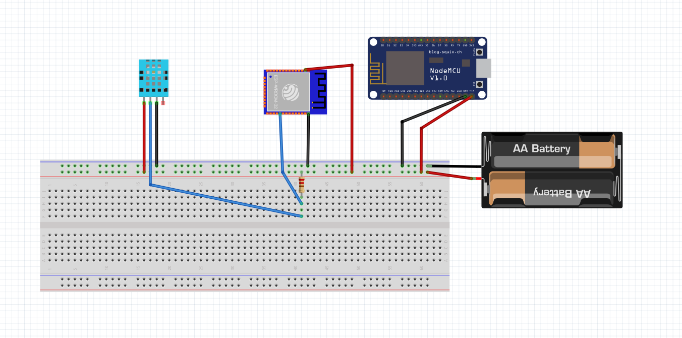
To connect all components and enable both codes to work (the first code for measuring temperature and the second code for displaying on the OLED screen), it is necessary to understand how all parts communicate with each other. Here we will explain how to physically connect all components, system configuration, and communication between parts of the system.
ESP32: This device is connected to the DS18B20 temperature sensor and sends temperature data to the server over WiFi network. ESP8266 with OLED display: The second device connects to the same server, takes data from the topic “temp/#” and displays the temperature on the OLED display.
Connecting the DS18B20 sensor to ESP: The DS18B20 has three pins: VCC, GND, and DATA. Let’s connect the DATA pin of the sensor to GPIO5 on the ESP (as defined in the code as #define ONE_WIRE_BUS 5). Connect VCC to 3.3V or 5V pin on the ESP. Connect GND to GND pin on the ESP. Add a 4.7k$\Omega$ resistor between DATA and VCC pin for signal stabilization. Connect the ESP32/ESP8266 via USB cable to the computer or adapter. When the ESP connects to WiFi and the server, it will read the temperature from the DS18B20 sensor and send it to the server on the topic “temp/zivinice”.
DS18B20 is a digital temperature sensor that enables precise temperature measurement in different environments. The sensor has the ability to measure temperatures in the range from -55°C to +125°C. Under standard conditions, it provides accuracy of ±0.5°C in the temperature range from -10°C to +85°C. It supports programmable resolution between 9 and 12 bits, where higher resolution enables more precise readings but requires more time for measurement.
This sensor uses the 1-Wire protocol for communication with the microcontroller, meaning only one data pin is needed for exchanging information. Also, each DS18B20 has a unique 64-bit serial address, which enables sensor identification in systems with multiple sensors connected to the same pin. The sensor power can be provided through the classic VCC pin or in “parasite power” mode, where it uses only two pins, data and ground.
DS18B20 can be used in standard and harsh conditions, thanks to versions with waterproof housing. This makes it suitable for measuring temperature in liquids, outdoors, or in industrial processes. The sensor is compatible with power supply from 3.0V to 5.5V, which enables operation with a wide range of microcontrollers, including ESP32, ESP8266, and Arduino.
For connecting to the microcontroller, the DATA pin of the sensor is connected to the GPIO pin of the microcontroller, while a 4.7k$\Omega$ resistor is added between DATA and VCC pin to stabilize the signal. If it is necessary to use multiple sensors on the same data pin, all sensor DATA pins can be connected together.
The sensor is often used in projects that require reliable temperature measurement, such as heating and cooling control systems, temperature measurement in different environments, and automated industrial applications. Its simple integration with microcontrollers and support through popular libraries make it one of the most commonly used temperature sensors.